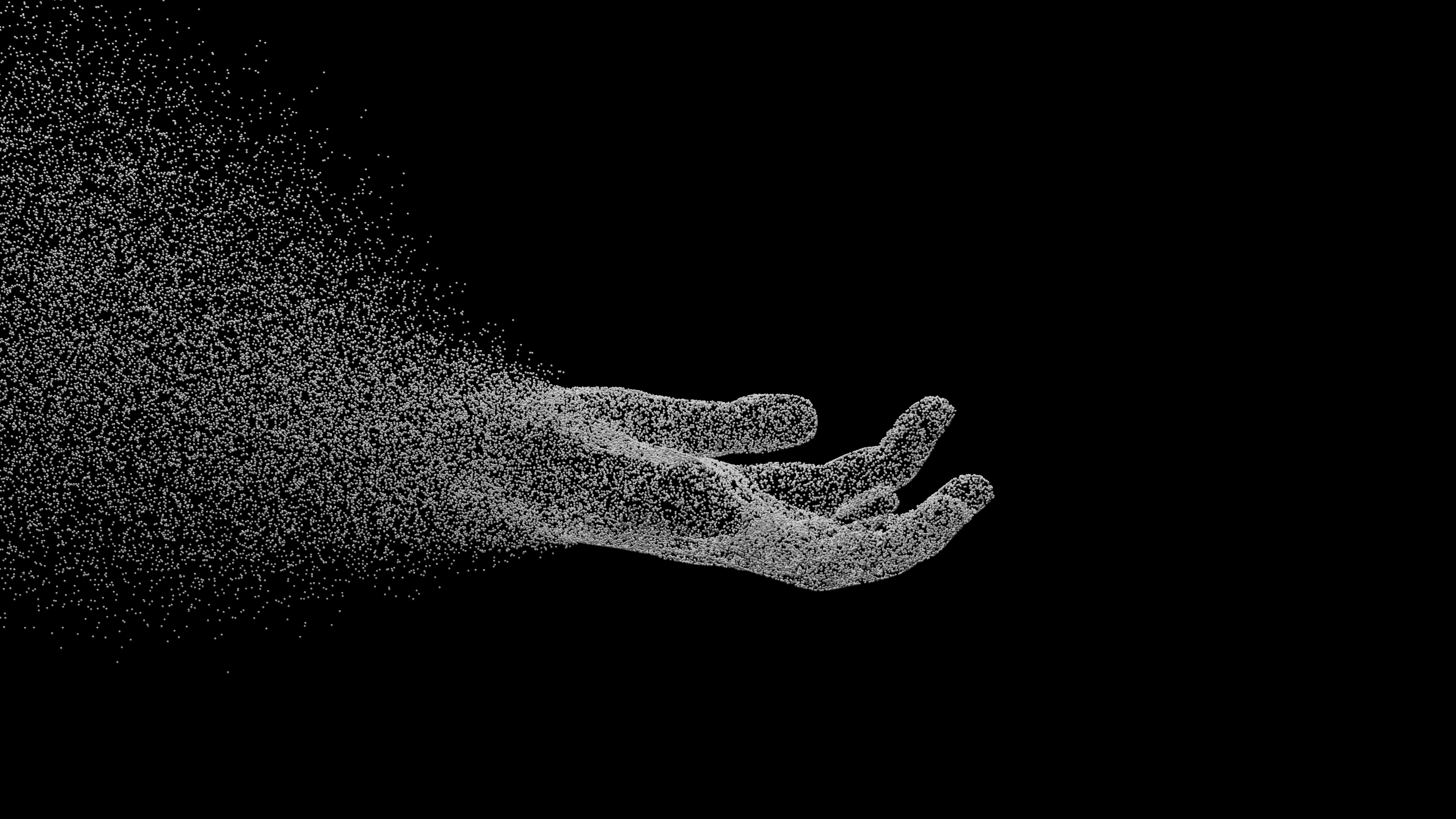
A few months ago we embarked on a journey to set up our own hand tracking pipeline for iPhone capture sessions. Having iterated on our offline stack substantially, we decided it was time to
a) create our own metrics dataset captured with real sessions from our actual hardware stack and
b) start thinking about the future of our own in-house model training.
We felt the first task to be important as a realistic grounding for our metrics, as many research datasets obfuscate raw sensor data with intermediate processing or have differences in optics and hardware that could shift our numbers or mask improvements and/or regressions particular to our setup, and the latter point felt essential to pushing forward at the edge of the space and getting the best possible performance.
Setting up hand tracking with off the shelf models nowadays is relatively pain free compared to spinning up your own solution from nothing, but many of these models (particularly the ones permitted to be used non-commercially) are trained on datasets that are relatively constrained and typically have low environmental variation. Additionally, much of the available datasets are created with low distortion pinhole model cameras or captured with a custom and expensive tracking system that requires investment to scale.
By comparison, real world data is captured across a variety of environments, with a large range of possible distractors. Furthermore, the appearance of hands in the real world is often more varied than the more academic datasets, both from a biological standpoint but also in condition. For example, hands may be tattooed, wet from performing common cleaning tasks, bruised, or soiled from dirt and oils. Many of the systems we have created internally for hand tracking are specifically post processing or between the detection stage and hand pose inference stage to address the difficulties of real, messy, and unpredictable captures from off the shelf cameras. Distortion effects, motion blur, tracking dropouts, lighting variations (including color temperature, brightness ranges and flickering) account for just a few of these additional hurdles.
Given this, we did not find academic or publicly available datasets at the time to be representative in testing our performance for our real recordings, so we felt the need to create a pipeline to enable us to make those considerations for ourselves. Additionally, the ability to create reliable ground truth data allows us to create our own pose distributions based on performance feedback.
To achieve this we decided to take a chance at using motion capture data, captured in tandem with a real session from the iPhone to create a metric test dataset. After connecting with a Vicon based motion capture studio in the area, we created a day plan and quickly got our feet wet.
We went in with a shortlist of task scenarios and hand pose movements that felt somewhat representative of common tasks we see in the field, as well as some sessions purely to cover the wide range of expression and range of motion that our hands have both in the center of the frame and out to the edge. Based on our experience working with existing models and where they have pain points, we created challenge cases such as crossed hands, hand-on-hand interaction such as interlocking fingers, and movement at speed. Once we settled on a shortlist and got introduced to the wonderful studio staff we had a quick briefing on the system capabilities and got suited up.
As the capture volume we were going to be working with was designed for full body, we had to suit up in motion capture suits. If you've never worn or seen them, it’s akin to dressing up like a deep sea diver that’s been covered in some sort of rare barnacle that’s taking over the host. The suits themselves are quite fitting to prevent the markers sliding during motion, and it felt quite alien. The system is Vicon based and we follow the Shogun guide for setting up.
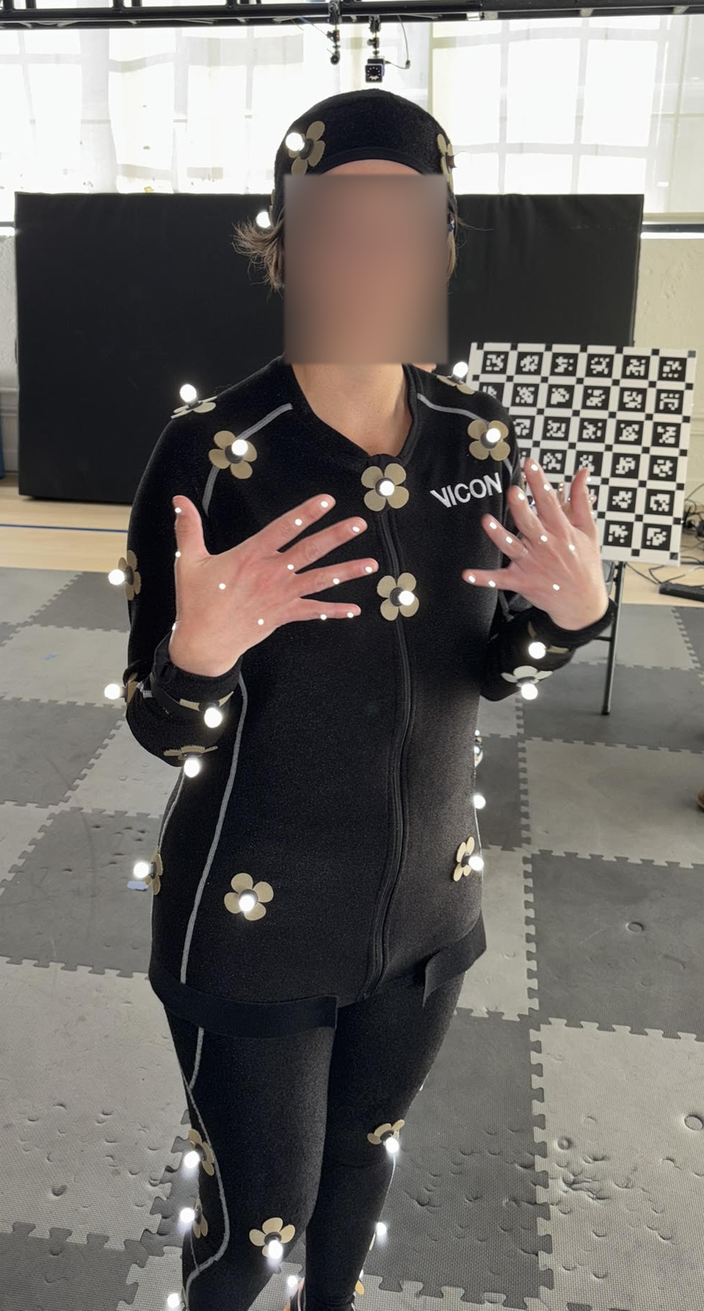
For tracking the hands, we followed the 12 marker layout. Importantly, we used hemisphere markers that sit on the skin. It is important to note at this stage the exact layout that each person varies as there's no well defined way to relate from one person's hands to another and the placements are approximate. To account for this we took recordings of the performers hands after markers were applied with the capture rig from multiple angles to create a mapping to our hand tracking system in post.
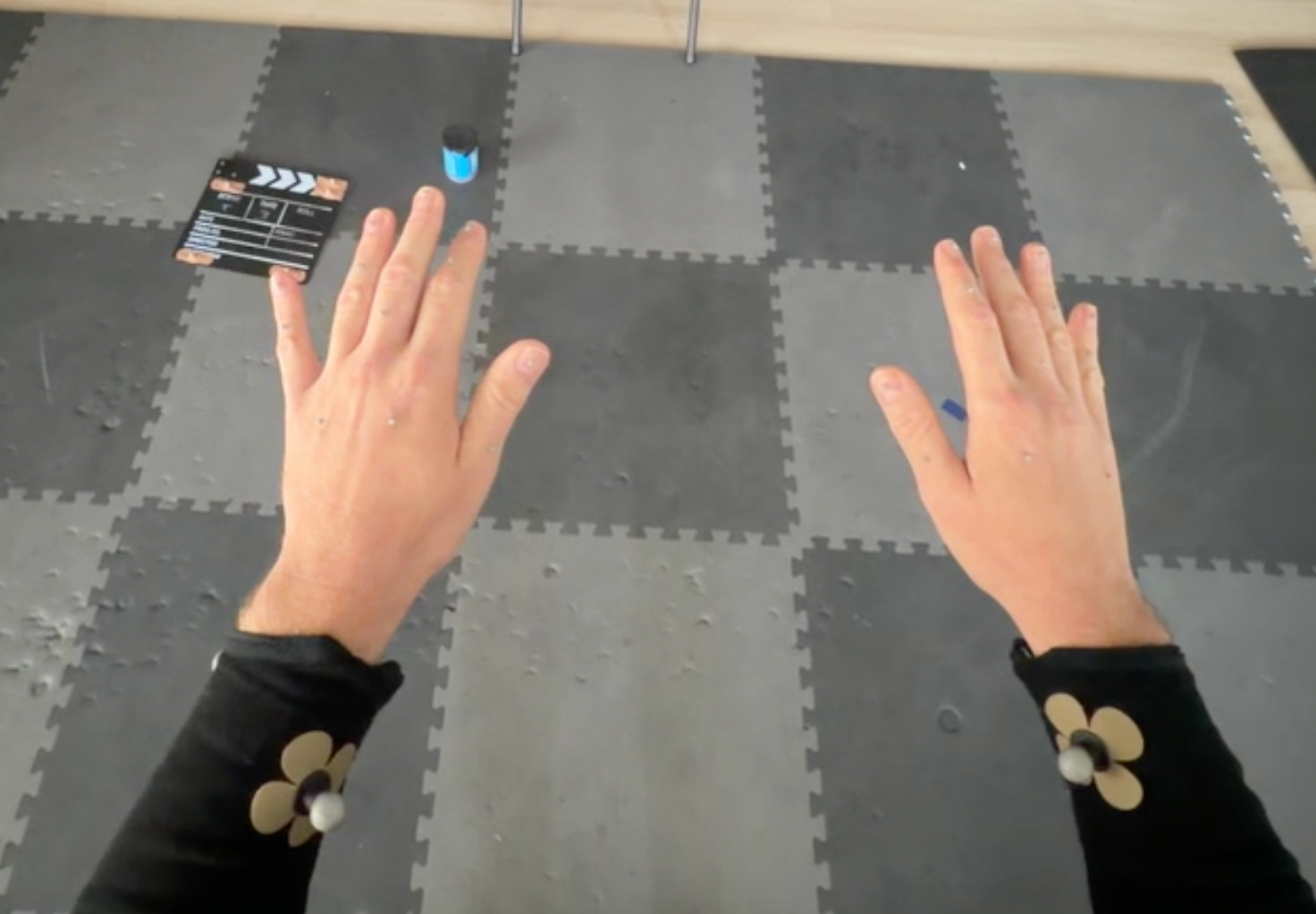
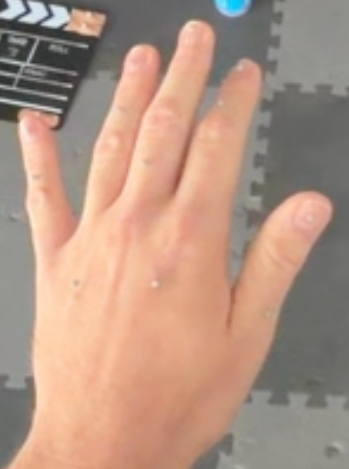
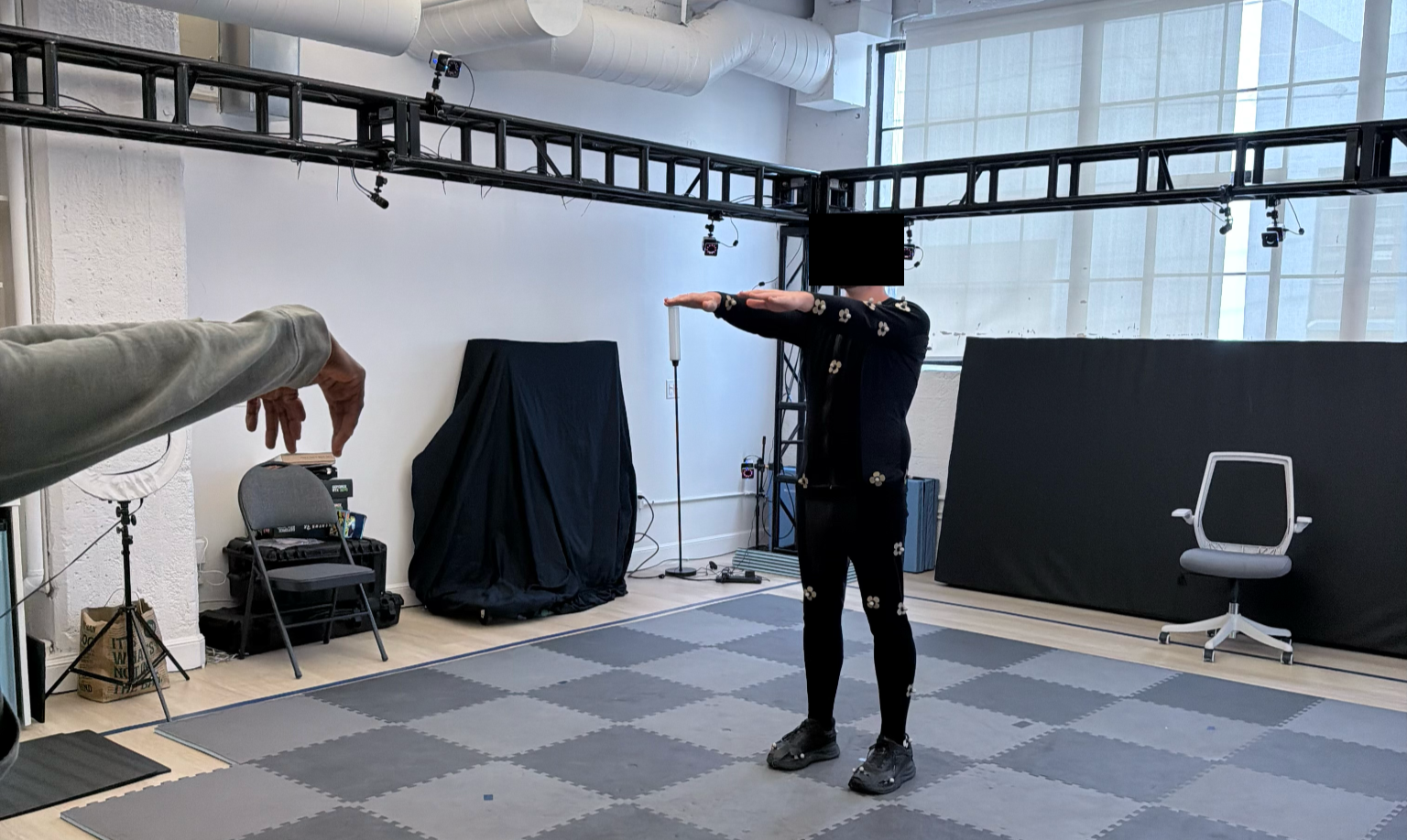
Now that we had been suited up and were ready to go, we went and began capture. The first thing to note is that we have two independent capture systems, the motion capture system and the iPhone capture system that we were building the metric for. To make the data usable, we have to go through this process of synchronization, and to do this we needed to come in prepared with the tools to ensure the data would be usable.
What do I mean by synchronization? I mean synchronizing the iPhone capture to the motion capture studio data in both SPACE and TIME!
NB: This process is also commonly referred to as 3D registration (though it should really be called 4D registration given the time aspect)
Time comes first, since we need to align all of our systems on this axis for anything else to have a chance at solving. The iphone shoots video at 30fps and our Vicon system is at 120hz.
For time alignment we took a very classically inspired approach from film. Since the highest sample rate in our data comes from audio, we picked up a clapper board and stuck a bunch of markers onto it. We would then have three points of synchronisation, the clapper sound, the RGB video of the clapper closing, and then high framerate capture of the marker positions where we could derive a min distance at the clapper closure point to signify the closing of the hinge.
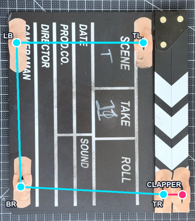
To match the audio, we took the impulse onset times from the audio recordings. We found this important to do since often the audio peak would come a fair bit later.
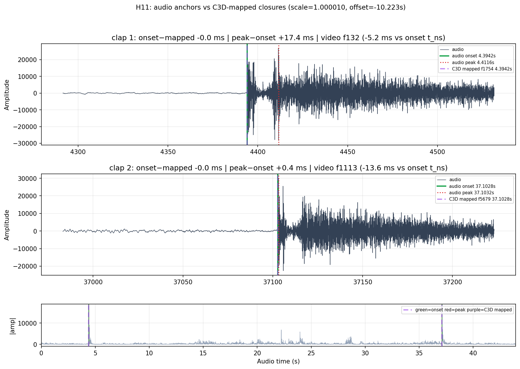
The audio timestamp is much more precise than eyeballing the video at 30fps, though we still used the video as a sanity check, and we then aligned this timestamp with the Vicon reported closure event to align the systems in time.
HAND EYE CALIBRATION
As many of those working in robotics will be familiar with, when working with multiple camera systems it’s convenient to have all the data be in the same frame of reference. For evaluating hand tracking results in the camera frame it's also a requirement for us to get the motion capture marker data into the frame of reference of the iPhone camera.
The Vicon system tracks the iPhone via a phone case that has a cluster of rigid markers attached, but it's not immediately obvious from those markers where the exact optical center of the iPhone camera is. To align the camera system coordinate frames we need both a position that matches the center of the camera sensor, as well as an orientation that tells us precisely the direction the camera is pointing.
We can get an approximate location for the camera by placing a tracking marker directly on the lens, recording what's known as a prop layout so we have the lens location relative to the other case markers, and solving backwards from that for the lens position in real sessions where we remove the obstructing marker from the lens. However, the offset of the lens from the sensor itself is already a few millimeters which can drastically affect the metric, and it doesn't give us an orientation, so directly using a lens marker serves mostly as a sanity check on the problem I'm about to describe.
To truly do this we need to use a visual anchor in the scene that both camera systems, Vicon and iPhone, can see clearly. This then gives us something known to connect the information from the two systems. We used a 6x6 AprilTag board, which we placed near one edge of the Vicon volume, and loaded it up with tracking markers around its edges. Since the board is a set size, we can calculate the camera's position from its visual presentation in the iPhone's FOV, and the Vicon system simultaneously tracks the exact position of the board via its edge markers. We used two markers per edge, enough to draw a line, but discovered later that 3 would have been more ideal due to potential dropouts over time (A lesson in redundancy planning).
Each clean video frame therefore gives us one observation pair: "where the iPhone camera says the board is relative to itself" with "where the iPhone rig and case cluster is relative to the board" . Stacking many of these observations lets us solve for the constant transform between the iPhone camera origin and the iPhone case cluster tracked by the Vicon system. This is essentially what's known in the robotics space as a hand-eye calibration, which you can read about more in depth here: https://www.mathworks.com/help/vision/ug/estimate-pose-of-moving-camera-mounted-on-a-robot.html.
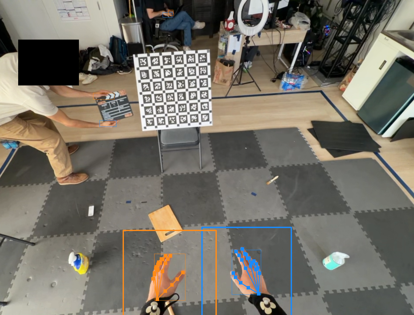
Despite feeling relatively simple, several challenges with the robot eye calibration presented themselves. From an operational perspective, an operator in the motion capture suit has no way of actually seeing what they're capturing, since the phone is strapped to their forehead, and as a result the number of frames that captured cleanly the view of the april tag board were quite limited in review. Additionally, due to the low light in the tracking volume (a requirement due to needing to control the light in the room for the visibility of the IR trackers) many of the frames that did have the apriltag board in frame suffered from a degree of motion blur due to the iphone compensating exposure with shutter speed. Even in slow near stationary frames, some frames were blurred to a degree that meant that CV accuracy on the tags dropped below our minimum threshold that was set to ensure accuracy.
The solve itself also has geometric requirements beyond just seeing the board clearly. Tag pose estimation works best with perspective diversity — multiple viewing angles of the board, since it relies on how the tag geometry changes under perspective distortion. But the hand-eye solve has a second, independent requirement: the head has to rotate between observations. If the camera sees the board from the same orientation every time, the system of equations is degenerate no matter how sharp the detections are. We book-ended our sessions by looking at the grid from the same start/end position, which gave us little of either kind of diversity, and a number of sessions got scrapped from our original corpus as a result.
In future recordings we might have more distributed tags across the volume, as well as create a more robust process for the calibration at the start and end of the session, including a more deliberate sweep of angle rotations and camera positions with the board in frame to generate good solves. As also noted before, additional tracking markers on the tag board would also improve its visibility to the motion capture system in cases where we might lose tracking on one of the edges temporarily, though this was largely solved by doing infill on board markers where we were able to confirm no drift or board position shifting over time.
Robot-eye is essential for us to transform our data into camera space to evaluate our motion capture system independently of any SLAM pipeline, but to evaluate full end to end performance in world space with our SLAM tracking in the loop, we also created a process alongside our robot eye calibration.
The SLAM system also creates its own camera transform, similar to the result of our hand-eye calibration, that needs to relate to the Vicon tracked iPhone cluster. We consume the calibration result we get from robot eye calibration to get a trajectory based on the Vicon tracking and then we use a rigid transform to make sure we can align the slam coordinates to it. We deliberately leave scale out of the fit though, since we just want to rotate and offset the origins to align the two frames without trying to alter the data in any way that would just shift the metric. In practice once we do this with our latest SLAM stack we found that it only accounts for less than a millimeter of the metric error we report in the pooled mean, showing that it doesn’t add a systematic bias. A big win for depth conditioned SLAM!
Much of the alignment and calibration we describe above is dependent on having tuned a lot of data filters to remove samples where we had noise, dropouts in data, motion blur heavy frames, or poor solve conditions. Additionally there was a lot of iteration on geometric solves that I won't cover here which were important in recovering tracked positions and geometry from raw motion capture files that took time to get right. This 3D registration step is by far the most important part of the entire pipeline, so managing tolerances in which samples you use to solve, and pooling the correct solves together to improve statistical power is essential.
Learning how to capture a clean mocap is a bit of a process, the accuracy of the marker tracking relies on maintaining high visibility to multiple cameras at any one time. Many of the poses we worked with, whether gripping objects, being close to the body, or self occluding, could cause subtle tracking dropouts in the sessions from the Vicon perspective. Because of this, many sessions needed several iterations and there was a learning curve for the performers to learn the ranges of motion and ways of holding that retained clean tracking. This creates a gap in our testing data that should be looked at with scrutiny. Other hand centric tracking setups tend to use a much smaller volume with a high camera density to get around this, and we’re hoping to bridge that gap soon. For the existing data, close auditing of the ground truth data is required to check that alignment of the mocap marker data overlaid onto the video checks out, and that short infill spans are valid. If not, we can exclude frames from the metric.
Finally, let's take a look at how we define our metric and set it up naturally for our tracking scenario.
Hand tracking models often report their success in MPJPE, Mean Per Joint Position Error. This is calculated by comparing the “Ground Truth” of a ball and stick model that represents the bones and joints of the test dataset, and comparing it to the generated bone and joint positions of whichever hand pose model has been deployed. However, it's immediately clear that there are shortcomings here.
Taking this into account, the natural mapping for our data is to instead track points on the surface of the hand. This is already the default mode for the Vicon trackers since that is where we place them, and is easy enough for us to get from our model since we output a MANO mesh of the hand.
To create our metric, we first need to establish where the markers on the hand correspond to points on the mesh. Since the placement of markers on the hand is a loosely defined process “https://help.vicon.com/space/Shogun110/13074940/Place+markers+on+a+performer”
It's required to create a mapping per performer on the day.
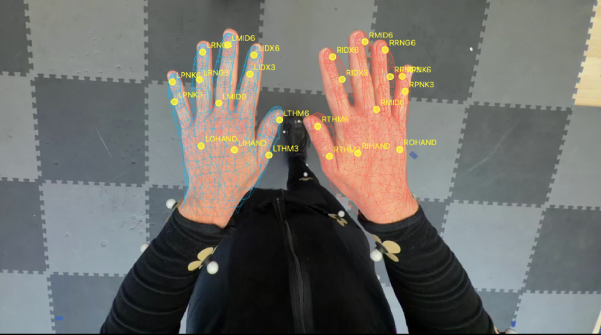
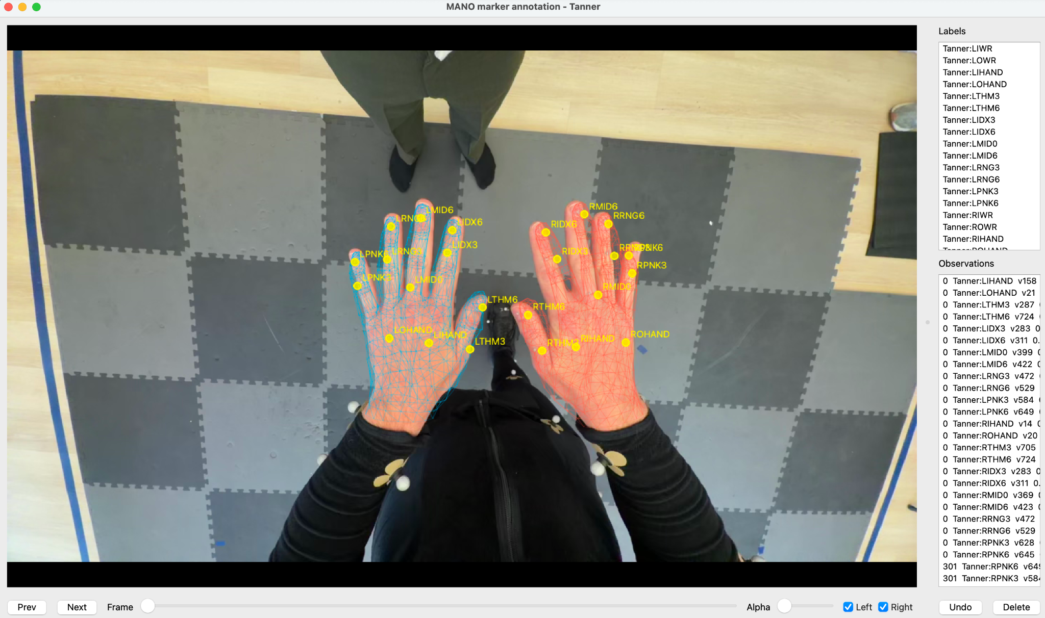
Before the sessions were recorded, we took a session recording of each performer’s hands with the markers clearly visible from a variety of angles. In post-production, we applied our inference pipeline to generate 3D hand meshes fitted to the hands. We then reviewed the frames manually, identified those where the estimated mesh aligned well with the hand, and marked the corresponding mesh location for each physical marker.
Any single annotation may contain some placement error, so we annotate each marker across many well-aligned frames. For each marker, we first select the mesh triangle that received the most consistent annotations. We then take the median barycentric coordinates of the annotations lying on that triangle.
These three barycentric weights define a stable point inside the selected triangle as a weighted combination of its three vertices. Because that point moves with the deforming MANO mesh, it gives us one consistent surface anchor for each physical marker and performer.
Annotation tool
Setting up the mocap captures provided a number of challenges both in the performances on the day as well as 3D registration pipeline setup. We learned a great deal from going through it, and hope that as we continue to improve on our process we can capture more complex motion, create more multimodal hand datasets including other modalities such as force, and perhaps even integrate body tracking data. As we look forward to both improving our existing stack as well as testing new hardware, we believe having the power and experience to create our own validation data across a variety of motions and scenarios is invaluable, and to that point we already have deployed it within our own research where it helps guide improvements in tracking stability and accuracy.